
While I was putting together this post last month, it dawned on me that doors are represented differently in plan, elevation and sectional orthographic views of a building. By which I mean:
- In plan, doors are generally shown in the open position.
- In elevation, doors appear closed.
- When cut through in section, doors disappear altogether.
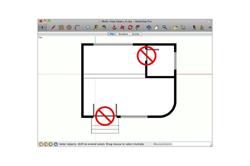
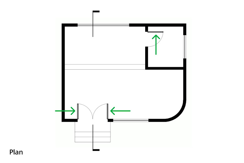 In plan, doors appear open to show their swing. In the above image, the swing arcs, section cut graphics and arrows were added in LayOut.
 In elevation, doors appear closed. Otherwise, you'd be able to see through them, which would be visually confusing. The scale figure and the dashed lines to indicate the hinge position were added in LayOut.
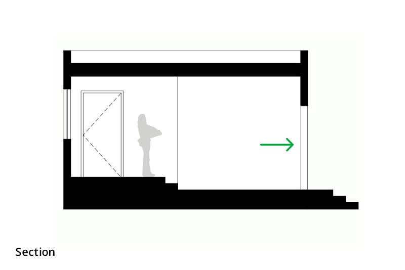 In sectional views, doors which are cut through don't appear at all. All that is visible of the doorway in the above section is the edges of the wall beyond the cut. Doors which appear in elevation (like the one on the left) are shown closed.
If I’m modeling a building and I leave the doors open, they’ll look correct in plan but not in other views. If I close them, the plans will look wrong. Clearly, I need two sets of doors—one open, one closed—and I need to manage which set is visible in each view. Layers, Scenes and nested components to the rescue!
The idea here is to create a door component that includes two sub-components: one that’s an open door, and one that’s a closed door. Mine looks something like this:
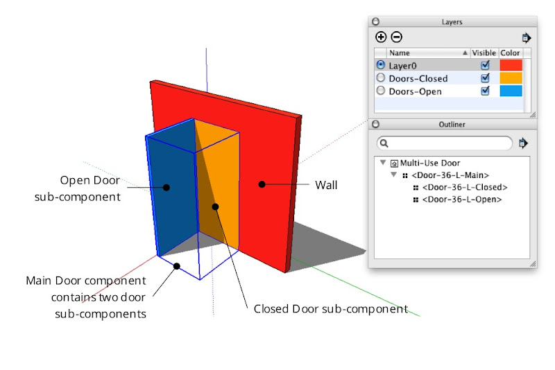 A door component which includes both open and closed door sub-components, each on its own layer. In the image above, "Color By Layer" is turned on to better illustrate the setup. The Outliner dialog box shows the nesting relationship of the three door components.
Creating a combination door component
Start by modeling both doors and turning them into a set of nested components:
Step 1
Create the hole into which you want to insert a door.
 Make the hole exactly the same size as the door you're planning to model.
Step 2
Model a door in the closed position. Keep it simple; a rectangle is fine for now.
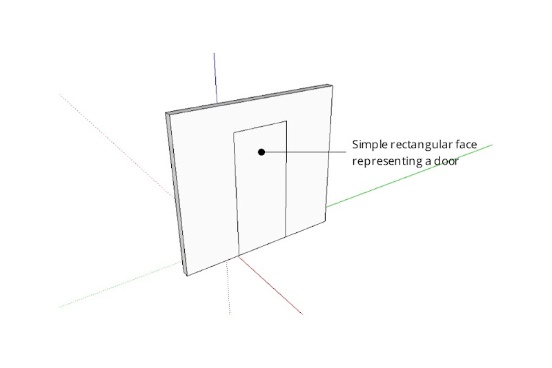 Fill the doorway opening with a simple face. Make it flush with the side of the wall into which the door will open.
Step 3
Select only the door geometry and turn it into a component. Give it a meaningful name that describes its size, orientation and position like “Door-36-L-Closed”.
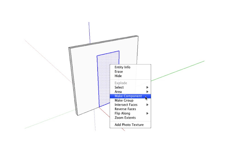 Turn your simple door into a component by selecting its geometry and right-clicking to open a context menu.
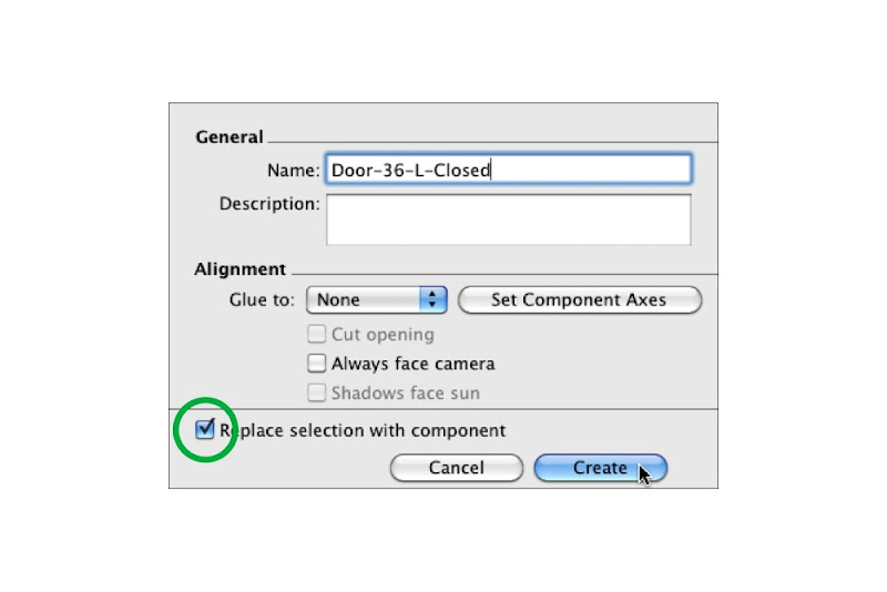 Give your door component a meaningful name; "36" indicates the width and "L" indicates the left-hand hinge position. Make sure the "Replace selection with component" checkbox is selected before you click Create.
Step 4
If you like, add detail (like a thickness) to the door you just modeled.
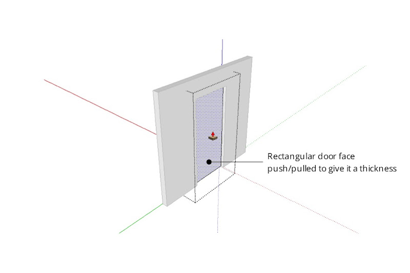 Extruding the single face into a 3D object will make it read better in plan. Resist the temptation to add doorknobs, detailed woodwork or anything else that isn't in keeping with your model's current level of detail.
Step 5
Model the same door in the open position. Be sure not to duplicate the component instance you made in the previous step — the whole point of this exercise is to have two, separate components.
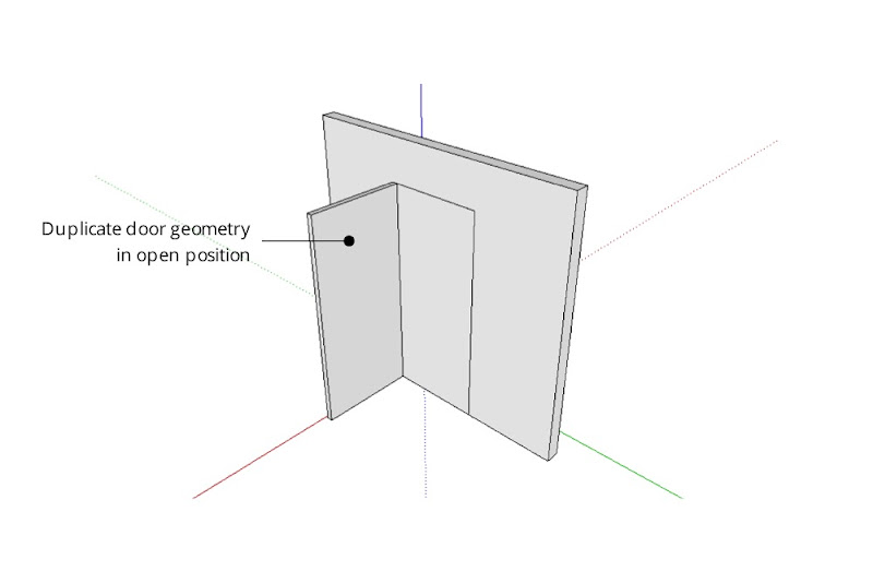 Model the same door again, this time in the open position. For accuracy, line up the edges where the hinges would be on a real door.
Step 6
Turn the open door into a new component. Call it something like “Door-36-L-Open”.

 Make the open door into another component and name it accordingly.
Step 7
Select the open and closed door components and make a new component that includes both. A good name for this component might be “Door-36-L-Main”.


 Select both door components (open and closed) and make them into a new component.
Using Layers to control component visibility
The next step is to put each sub-component on a separate layer:
Step 1
Choose Window>Layers to open the Layers Manager.
Step 2
Create a new layer called “Doors-Open”.
Step 3
Create another layer called “Doors-Closed”.
 Use the Layers Manager to create two new layers.
Step 4
Choose Window>Entity Info to open the Entity Info dialog box.
Step 5
Start editing your Main door component (the one that includes both sub-components) by double-clicking it with the Select tool.
Step 6
Select the closed door sub-component and move it to the “Doors-Closed” layer using the Layer drop-down menu in the Entity Info dialog box.
 Move the Closed Door sub-component to the "Doors-Closed" layer using the Entity Info dialog box.
Step 7
Select the open door component and move it to the “Doors-Open” layer.
 Put the Open Door sub-component on its own layer, too.
Step 8
Click elsewhere on your screen to stop editing the Main door component.
 Make sure the Main Door component (which includes both sub-components) is on LayerO. If you're really advanced, I suppose you could even have a layer dedicated to these "combo" door components. Tread lightly, though—layers can be tricky to work with.
Setting up Scenes to control layer visibility
After you’ve placed doors wherever you need them in your model, you can control which set is visible by creating (or updating) scenes that show only one “Doors” layer at a time. It’s pretty straightforward, really:
Step 1
Activate the scene that corresponds to a plan view of your model. If you don’t have one yet, just create a new scene called “Plan” and worry about getting the camera position in order later.
 Right now, both the Doors Closed and Doors Open layers are visible. We only want the open doors to appear in the above plan.
Step 2
In the Layers Manager, hide the “Doors Closed” layer.
 Uncheck the Doors Closed layer to make its contents invisible.
Step 3
Right-click the “Plan” scene tab and choose Update.
 When the doors look the way you want them to, right-click the relevant scene tab and choose Update.
Step 4
Repeat the above three steps for any other planimetric scenes in your model.
Step 5
Go through the above process again for any scenes where doors should appear closed.
 In the above elevation view, I want only the Doors Closed layer to be visible.
Dealing with doorways in section
What about doors that are cut through by section cuts? They shouldn’t appear at all. The solution here is simple: Just hide the offending door components and update your scene.
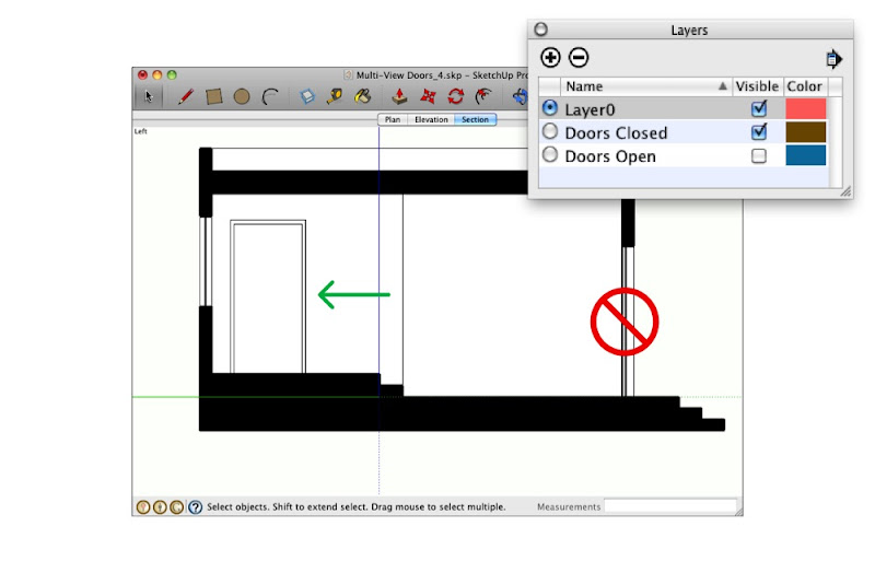 Doors which are cut through in sectional views shouldn't appear at all. Those which appear in elevation (like the one on the left) should appear closed.
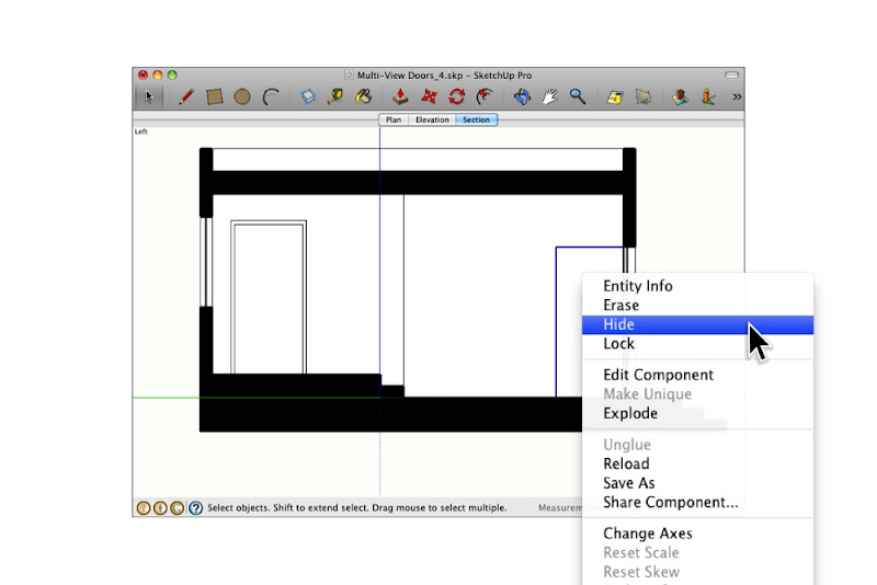
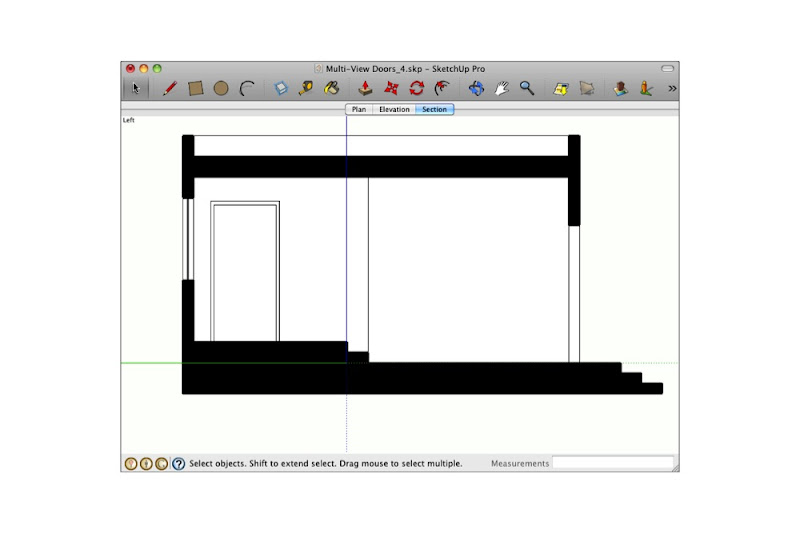 Simply hiding door components you don't want to see (then updating the corresponding scene) is the easiest way to deal with this conundrum.
One more thing: I've added the above example model to the 3D Warehouse so you can download it and do some of your own experimenting. You can find it here (click the 3D Warehouse logo to go to the model in the 3DWH):

12 comments :
Someone had a plug-in that made all the permutations of doors open, 45, 30, closed on their own layers. I forgot the name of th eparticular plug-in, but I think it was British.
smart & simple
Nelsong was it the Door Maker plugin by any chance.
I have this plugin and it has increased my work flow productivity by about 25% it is simply fantastic. It is completely automated with lots of features for customizing the set up of your doors. (Vision Paneles/handles/name and kick plates)
I tend to then go even one step further by
a. Making the all my door heights the same (if unknown) and making sure that I make one door component that is then copied into position after running the ruby only once for that particular width of door. Therefore affording you more flexibility when using perspective views. Say for example 10 double doors, 6 doors at 900mm wide and 4 at 950mm wide.
b. Create a layer with door swing identifiers on it. Allowing you to create dashed lines with the divide and erase tools (these with then save you time in Layout as you only have to do it on one door and it will then be done on them all.
Great ! We were just talking about such a trick last time with Bertier.
In SU issues are solutions !
Thank you for sharing.
http://modelisation.nancy.archi.fr/rld/plugin_details.php?id=117
Door Maker plugin
Can Sketchup have linetypes so that we can add hinge position for Architectural Elevations that we show on our conventional drawings and also
for plan views we would always add in the door swing arc too but that can be added to the component.
I have been creating architectural sets for 25 years. I have literally seen hundreds of sets of plans.From hand drafting to AutoCad to Sketchup.
Door open in plan and closed in elevations has been standard format the WORLD over for decades. Why all of a sudden is it. I have never once heard a complaint in my life.
There is good reason for this.Showing the hinged side clearly.
Why is showing them the conventional way all of a sudden "incorrect?"
If you want to take the time to develop some way to show doors one way or another, go for it, but strikes me as a trivial and complete waste of time.
Signed, drafting pro.
I shall rephrase,
"on our conventional Sketchup drawings and in layout too"
:)
Happy Sketching
really a nice topic to discuss here... n its appreciable d way u hav handled it... really interesting... nvr thought in dat way... good keep it up... i jst hav a querry how can v show the section in sketchup with filled walls... they look see through whenever v cut them...thnx...
Your measure is exactly perfect to put door in that area and your diagram has standard format..Thanks for sharing...
-------
Map model
Maybe construction standards are different elsewhere, but in the USA, your door swing terminology is backwards. To determine the "handing" of a door, put your butt on the hinge jamb. Whichever way the door opens is the handing.
In your example above, the door is a right-hand swing, not a left-hand swing.
Otherwise - great tutorial. Thanks for the tips.
Woodworkers should adapt their knowledge of door sketching that helps to design and build almost any type of doors. Your steps are beneficial for every woodworker to make a quality and exquisite door.
garage doors Perth
Post a Comment